 |
HINTS AND TIPS The Buttons below will take you through the different hints and tips that I feel will make your helicopter safer and more reliable. |
Fixing
the Overhead wiring Panel |
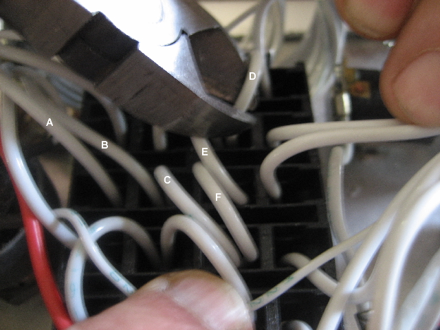
It is up to each builder to determine which modifiactions to perform on their own helicopters. If your ship has the jumpers as installed from the factory in the overhead wiring panel, all engine systems could shut down simultaneously if a short circuit should occur. The following photos and explanations show how I fix this problem to provide true redundency to the electrical power to the engine components controlled by the overhead panel. Step one is to disconnect the battery and then clip back the plastic zip ties that bundle the wires together so that you will be able to pull the wires to one side to get to the three jumpers (D,E, & F) that go between Fadec 1to Fadec 2 to Ign 1 to Ign 2. These jumpers connect both the primary and back up systems together and will cause those systems' power supply breakers to blow in the event of a short circuit in the alternator wiring (B). Once you can get at the wires you can easily see the three jumpers. I cut the first jumper (D) as close to the Fadec 2 fuse as possible to give me a longer lead to work with. The middle jumper (E) between Fadec 2 and Ign 1 is cut in the middle and the last jumper (F) is cut as close to Ign 1 as possible to give a longer lead on the Ign 2 side to work with. The below photo shows me cutting the Fadec 1 to Fadec 2 jumper (D). Wire (A) is the 30 amp lead coming from the battery to one of the two the 30 amp Battery fuses, (B) is the wire that comes from the alternator and connects to the 30 amp battery fuse on the load side so if there is a short in that wire, it takes out the 30 amp fuse, then through the jumpers takes out the other 30 amp fuse cutting all power to the engine systems. Wire (C) is the power wire coming from the load side of the 30 amp battery fuse to the line side of the Ign 2 fuse.
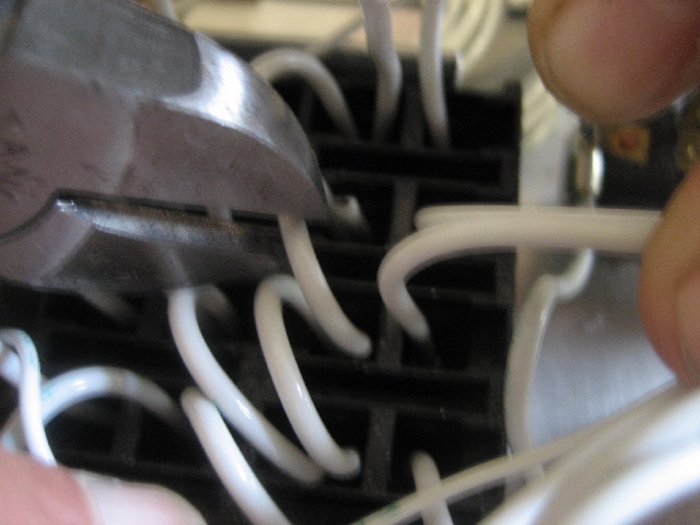
The below photo shows me cutting the jumper (E) between Fadec 2 and Ign 2 in the middle of the jumper.
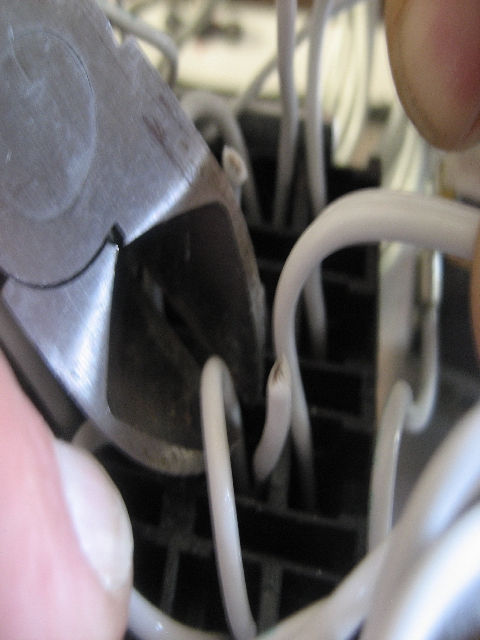
The photo below show me cutting the jumper (F) between Ign 1 and Ign 2 as close to the Ign 1 fuse as I can cut it.
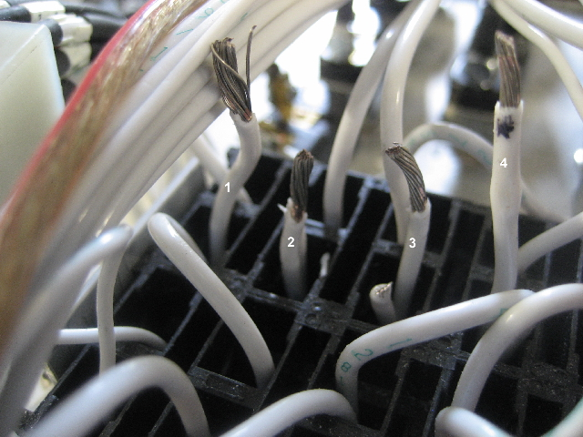
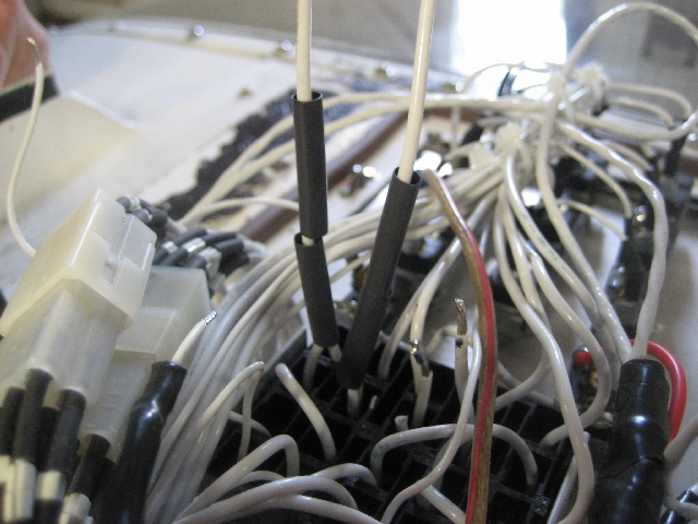
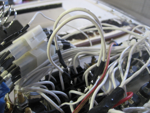
In the photo below the jumpers have been cut and the ends stripped of insulation so that the two new jumpers can be attached. I solder an 8" 14 gauge jumper between wire one (Fadec 1) and wire 3 (Ign 1). I solder another wire between wire 2 (Fadec 2) and wire 4 (Ign 2).
After I solder one end of each jumper to Fadec 1 (Wire marked 1 on above photo) and Fadec 2 (wire marked 2 on above photo) each, I slide two pieces of shrink wrap onto each new jumper so that I can insulate both ends of the jumper after the final soldering is completed.
The photo below shows the two new jumpers soldered onto the cut jumpers. One wire connects wire 1( in the photo with marked wires ) to wire 3 and the other jumper connects wire 2 to wire 4. Once the all of the joints are soldered, I slip the shrink wrap over the solder joints and use a heat gun to shrink the pieces in place. The short stubs of the jumpers that were cut (seen in the photo below) can have a piece of shrink wrap placed on them and then heat shrunk in place. Once the two new jumpers are installed and tested by turning on all systems, I use new zip ties to securely bundle all of the wires in the overhead panel together.
|
|