 |
HINTS AND TIPS The Buttons below will take you through the different hints and tips that I feel will make your helicopter safer and more reliable. |
Overhead Wiring
Overhead Wiring
-
The new Rotorway Talon has circuit breakers instead of fuses. The one that I inspected still had the three jumpers as discussed below and in my opinion they need to be modified as well. Of course that is my opinion, every owner needs to make their own informed decision.
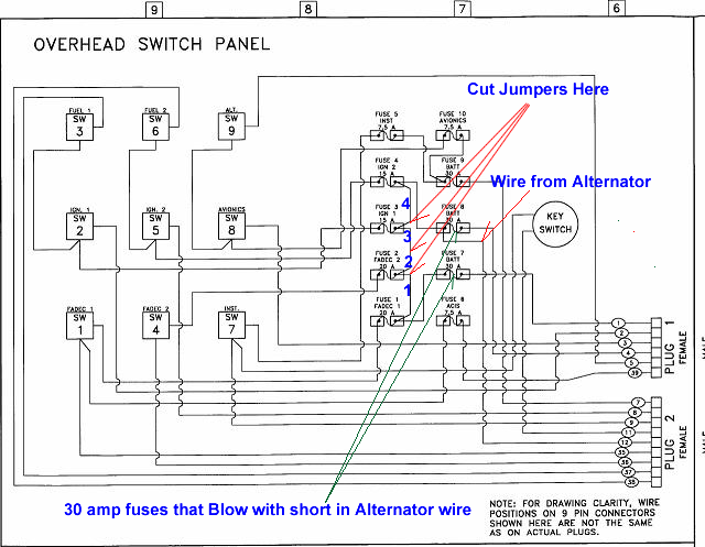
- The over head panel wiring has three jumpers that connect all of the engine electrical systems together. If the alternator wire shorts out, and I have had this happen on several ships that I was flying, the factory wiring allows the shorted wire to blow out the two 30 amp fuses that supply the power to the overhead panel from the battery and also the 30 amp fuse that supplies power from the alternator.
- When those three fuses blow out all power is cut to both your ships primary and back up Fadec computers, fuel pumps, and ignition systems, so your engine dies and you go down. I came up with this simple fix to what I call the fatal flaw because if it happens, it is fatal to the operation of your engine and if you are flying, you will be doing a real autorotation.
- You will need to decide if you want to have this wiring as supplied or do the modification to separate the power sources from your primary and backup systems.
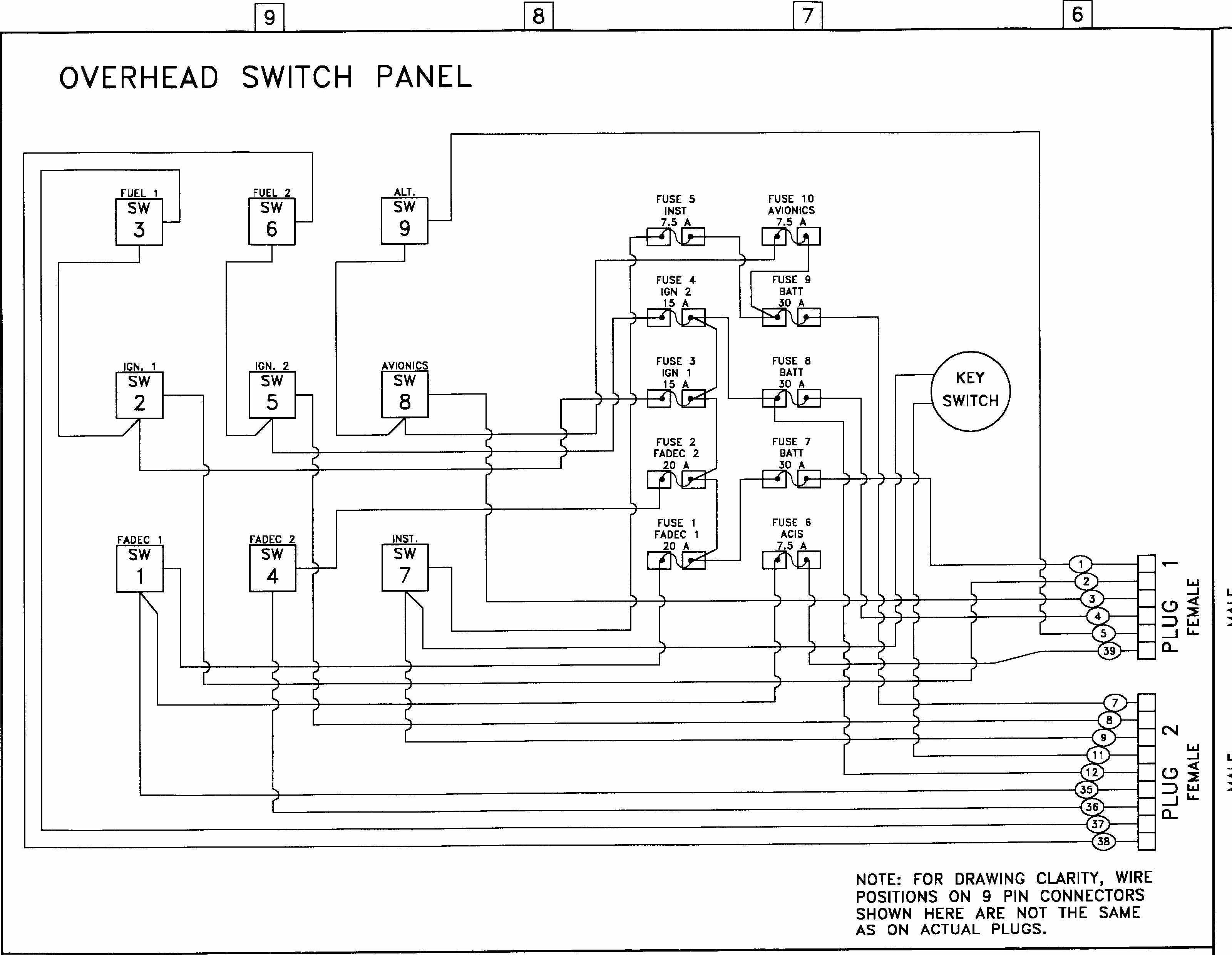
Below is a factory wiring diagram showing the circuits that you may wish to alter.
In the diagram above, I cut the jumper wire between fuse 4 and fuse 3 as close as I can to fuse 3. I cut the jumper wire between fuse 3 and fuse 2 in the center of the wire. I cut the jumper between fuse 2 and fuse 1as close to fuse 2 as I can.
| In the drawing to the right you can see the 3 factory jumper wires that I will cut, they are in red and on the right side of the photo. | 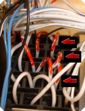 |
| In the photo to the right you can see the two new jumpers that are installed(orange). They were then secured neatly and firmly with wire ties and then spiral wire wrap was applied to the harness that exited the back of the overhead panel. | 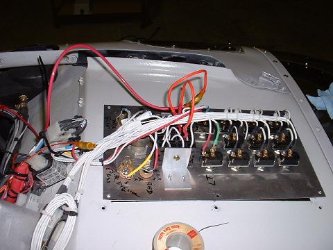 |
Click Here if you would like a description with more photos and step by step instructions of how I fix the Fatal Flaw in the overhead wiring.
If you own a Rotorway Exec 90 it too has a jumper between the ignition systems that you may wish to remove. Take a look at your wiring diagram and you will see that both ignition systems are tied together in the overhead panel so that if one shorts out it can take the other one with it.
Click Here for more general information on wiring.
| DISCLAIMER: The material on each page is the opinion of the author only and any actions taken by the reader relating to information on this site is the responsibility of the builder. |