 |
HINTS AND TIPS The Buttons below will take you through the different hints and tips that I feel will make your helicopter safer and more reliable. |
Tail Boom
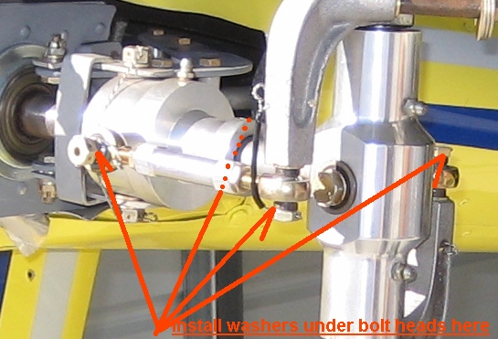
Washers on Tail Rotor Pitch Links Although I have never experienced such an event on the tail rotor pitch links, it is possible for the rod end bearing retainer to fail allowing the rod end outer casting to slip over the bolt head that secures it to the tail rotor mechanism. A simple safety modification is to install a washer under the head of each of the four bolts with a large enough diameter to prevent the rod end casting from being able to totally come off the bolt. If the bearing retainer should fail then the pilot would feel a vibration from the tail rotor area but the rod end should remain functional for enough time to allow an emergency descent and landing
The Slider rails on the Rotorway helicopter will wear with use and can become quite sloppy. I have seen them worn to the point of failure on at least one Rotorway helicopter. The factory plans direct the builder to drill a hole through the slider and the slider rail once the belts were stretched to firmly secure them from movement. I have seen this done and when I checked the tail rotor belt tension it was way on the loose side. The builder did not think that he needed to make any more adjustments after the initial stretchWrong! If this method is followed it is possible to end up with a series of holes drilled on the slider from multiple adjustments over the life of the belts. It is not a bad method but it takes additional time to remove the screws and nuts in order to adujust the tail rotor belt tension. One of my students had what he felt was a better solution that is pictured below. This aviation cable turnbuckle was purchased from Aircraft Spruce and Specialty and has forks on each end. The forks slip onto the rail and are bolted on beyond the 1 furthest adjustment mark. To adjust the belt tension he clips the safety wire that passes through the hole in the turnbuckle and is wrapped around the all thread rod. He then loosens the turnbuckle, tightens the belts, tightens the turnbuckle to clamp the rails against the slider firmly, installs new safety wire to prevent the turnbuckle from rotating.
In the photo above you can also see that the builder installed a tubular bushing on the rear portion of the all thread rod behind the jam nut. This gets the jam nut out in front of the rear aluminum angle where it can be easily reached with your 1/2" wrench each time you adjust the tail rotor belt tension. You will be glad you installed this simple modification. Below is a photo of the Aircraft Spruce and Specialty catalog where he ordered the turnbuckle. It is an AN 150-8S turnbuckle assembly. You can click on this link that I have provided to go directly to their order page for this turnbuckle. Remember that each builder is responsible for any alterations that he makes. I am simply sharing what others have done on their own helicopters.
-------------------------------------------------------------------------------- Once again I am posting an account from my personal experience to help you guys become aware of another issue that has surfaced from poor workmanship on the part of a builder. If you are aware of these issues, you will know what to look and listen for on your own ships before disaster strikes. Just yesterday I was providing phase one hover training with a student who purchased a partially assembled kit. He finished it himself and the work that HE DID was excellent. I had gone over this ship very carefully and found a number of small issues that we corrected before beginning hover training. After we landed following the 4th hover hour I noticed a slight ticking coming from the tail rotor area. I could not pinpoint the source of the ticking but it was in a rythmic pattern of sound with each revolution. When I asked my student if he has assembled the tail rotor shaft assembly he said that those components were already put together by the former owner. I told my student that it would be prudent to take the tail rotor assmebly apart to inspect the mechanism before further flight. We pulled it into my hangar and pulled it apart. We found that the former owner had drilled misaligned holes in the pulley and shaft and then had attempted to straighten out the misaligment by through-drilling which resulted in oblong holes. As the ship was now hovering the forces were allowing the pulley to wobble on the 3/16 bolt making the clicking noises. The hole in the pulley was a3/16 by5/16" oval by the time we found it and the bolt was severely worn and nicked by the relative movement of the TR drive shaft against the bolt in sheering action. The pulley to shaft bolt was certainly about to fail and the shaft would most likely have cracked in a short time if the bolt has not gone first- either happening during flight could have been disasterous. Keep an ear tuned to all parts of your ship. I find that it is helpful to listen to the rotorating components on run-down as the blades coast to a stop as sometimes an unusual sound will signal big trouble brewing. This is one more case of poor craftsmanship buy a former owner that is hidden and passed on to an subsequent unsuspecting builder who is an A&P with IA credentials and who teaches at an A&P training technical school. If it can escape my inspection and his inspections, it may not have passed your own inspections. Listen and learn. We are ordering a new shaft and pulley
from Rotorway.
|


| DISCLAIMER: The material on each page is the opinion of the author only and any actions taken by the reader relating to information on this site is the responsibility of the builder. |