 |
HINTS AND TIPS The Buttons below will take you through the different hints and tips that I feel will make your helicopter safer and more reliable. |
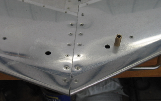
Everyone flying a helicopter needs to take special note of the vertical Stabilizer bracket and spar. This area should be checked carefully prior to every flight. While I was flight instructing in Idaho, we noticed that the vertical stabilizer was not solidly attached to the helicopter during our pre-boarding inspection. The photos below show the stabilizer with the broken bolt. |
 |
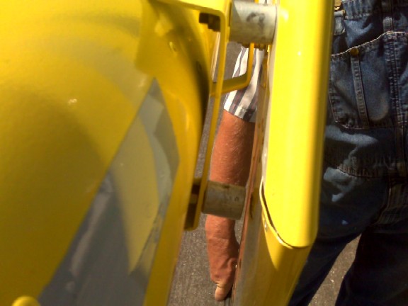
The
view of the missing bolt from the front. It broke where the spar
rubbed on the shank. Notice that the stabilizer did have the additional
rear bracket installed and that may have saved us from an in-flight
separaton by giving extra strength in that area when the bolt broke
in flight. |
 |
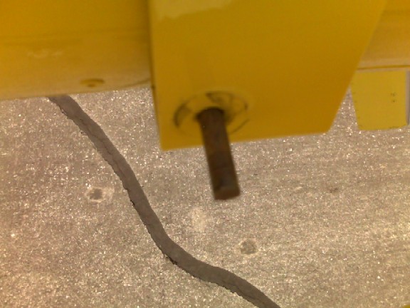
The
photo below shows the part of the bolt that was left attached to
the helicopter after the stabilizer was removed. |
 |
I now strongly feel that this area should have a bushing of some sort installed into the stabilizer spar that will prevent the spar from flexing (crushing) when the bolt is being brought to the proper torque and to prevent the sharp edge of the bolt hole in the steel spar tube from contacting the bolt. There are a number of ways to address this. One builder removed the bolts and then sprayed expandable foam sealant (as used for sealing gaps in household construction) into the spar tube through the bolt hole. He waited 24 hours for the foam to set. He then used a pick to clean any foam away from the bolt holes and then filled the voids around the bolt holes with 2 part epoxy(the stabilizer was flat on his work table which allowed him to pour the epoxy into the up facing holes while the down facing holes were sealed with some tape to prevent the epoxy from oozing out). The expandable foam formed a dam that prevented the epoxy from flowing away from the area of the hole. Once the epoxy was hardened he drilled the bolt holes through the spar holes and through the epoxy. This method seems to be a good way to achieve a bushing inside of the spar without removing the skin from the spar. I have talked with others who have taken the skin off and welded steel inserts into the spar for the bolts to pass through and others have inserted aluminum plugs in from the ends and pushed them up and into place and held in place with epoxy applied into the spar through the bolt holes just before the aluminum plug was slid into position. The aluminum plugs were then drilled through the existing bolt holes. I feel that the builder or subsequent owner should make some sort of bushing inside of the spar tube holes at the front of the stabilizer. There is a good amount of force applied to both the vertical and horizontal stabilizers during flight with up to 110mph air passing around them and the downward air pulses from the main rotors continually assaulting them.
I give each of my students a Pre-boarding check list that I have developed over years of observing those areas that can get a pilot into trouble during a flight. This simple check list is performed prior to boarding the helicopter every time. One of the items on the check list is to check the vertical stabilizer. This is done by grabbing the bottom of the tail stinger and applying pressure sideways while viewing the brackets and attachment bolts for movement. Jim was returning home from a breakfast meeting of the local flying club when the vertical stabilizer departed the helicopter. The stabilizer was found some distance behind the wreckage and a witness stated that the helicopter blades stopped turning while the helicopter fell vertically to the ground. The rotors showed no sign of rotational damage supporting the witness statement that the blades had stopped in flight. From the photos of the wreckage, it is evident that the bracket had broken allowing the stabilizer to move excessively, fatiguing and finally fracturing the other end of the front attachment bracket (part of which was still attached to the stabilizer). The stabilizer then blew back in the relative air flow ripping out the rear attachment bolt as it departed the helicopter. The pilot was most likely so distracted by vibrations associated with the breaking of the support bracket and the departure of the stabilizer that he allowed the helicopter rotor RPM to decay to the point of main rotor stall, the results of which are never positive.
The NTSB report stated that the cause of the crash was that the builder had drilled additional holes in his vertical stabilizer bracket (not per the factory drawings and instructions) and then did not de-burr the holes. A crack began at one of the burrs and progressed along the weakened bracket. The loss of the bracket was a survivable event. The pilot failing to maintain main rotor RPM was not. |
Clark
Richter provided us with a tutorial on how he modified the Vertical
Stabilizer on his Rotorway 162F. Click the photo below to go to
Clark's Tutorial |
||
 |
||
|
||