 |
HINTS AND TIPS The Buttons below will take you through the different hints and tips that I feel will make your helicopter safer and more reliable. |
Control Movements and Stops |
| Ease of control movement Controls should be smooth and not tight in all directions of intended travel.
|
 |
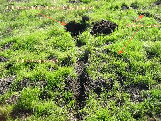
The below photo shows where we hit first (diagonal skid marks to the right), tipped forward onto the nose of the skids (see Rocking Horse skids) under the landing gear hints and tips) then the helicopter pivoted around the front left skid about 45 degrees to the left with the front of the left skid digging out a large divot of sod (the dark clump in the photo). The deep skid impression was made as we settled back level onto the skids, can be clearly seen in the photo. In this case the ground was very soft, as you can see in the photo. Instead of the left skid kinking at the front of the left landing gear weldment, which usually happens, the nose of the skid dug into the soft sod like a cookie cutter and as the ship pivoted around (tail moving to the left) the buried front left skid area, it cut out the piece of sod that you can see overturned in the photo. This instance was as close to a roll over as one
can get without actually going over. We found the reason for the
control lockup and fixed it right there where the helicopter landed.
We then did a very thorough pre-flight inspection looking for any
damage and found none. After about an hour on the ground, we fired
the helicopter back up, lifted off and resumed our flight training
and continued without problems for the rest of the week when my
student was soloed. After our flight I walked back out into the
field with my camera to take the below photo so that others can
see- proof positive- how the Rotorway helicopter reacts to a full
touchdown emergency landing with forward ground speed. The impressions
in the soft soil tell the entire story. |
||||||
|
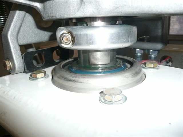
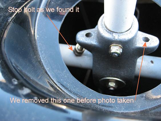
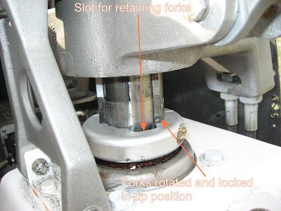
One other area where I experienced a control lockup in flight was with the donut-shaped collar around the main rotor shaft under the non-rotating swash plate on the Rotorway helicopter. This collar must be secured to the main shaft by clamping pressure so that it cannot slide up or down. In this case I was with a student when the collective controls locked in the near full-up position. This happened in an area where the wind was high and gusting higher as my student was making an approach to the fuel tanks on his ranch. Controlling the helicopter, a Jet Exec non-factory configuration, in the gusty winds was requiring a lot of collective input when all at once the collective locked in the near-full up position. It is important to note that the jet engine equipped ships vary greatly from the design of the Rotorway helicopter and their reliability history should not be compared with that of a Rotorway built to factory specs.
A word of caution here, we were in a life and death situation and the only way that I could stop the rapid climb was to reduce the main rotor RPM to decrease the lift being produced. Doing this in flight and especially in a high rotor pitch angle climb is very risky and if the rotor RPM is allowed to decrease much below that point the main rotors will stall and the helicopter will fall like a rock. I had no choice and did what I needed to do to cause the helicopter to descend and slide onto the surface.
Upon examination after the lockup we found that the clamping bolt had corroded threads. The bolt thread condition caused the nylock nut to achieve the proper torque, but before the nut was far enough onto the bolt to securely clamp the collar to the shaft. The person installing the collar must have used a defective bolt to secure it. I now gently but firmly pry down on the collar on every ship I apply downward pressure on the collar to insure that it has the proper clamping pressure so that it will not move. I also check the torque on both the nut and the bolt head to insure that both are at the proper setting to achieve the required clamping force on the collar.
|
 |
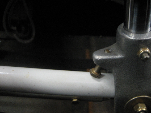
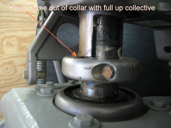
After we repositioned and securred the collar above and completed Ron's flight instruction, I headed to Pennsylvania to provide another student with advanced flight training. I was performing an airworthiness inspection on this student's Rotorway Exec 90 when I noticed the collar position looked too low. When I pulled full up-collective the fork came completely out of the collar. We checked the torque settings and they were incorrect for the nut and bolt head, they were loose. This student had been flying it that way at altitude and if he
had ever been put into the position of applying full up-collective
the fork would have come out of the guide slots and rotated away
from them. This would again have jammed the collective in the
full-pitch position. Had that happened it could have ended up
in an unhappy ending! Everyone should check the position and security
of this collar. That was the second collar issue found in 2 weeks.
The photo below was taken before we slid this second collar back
into position and properly torquing the clamping bolt. |
|
||||||
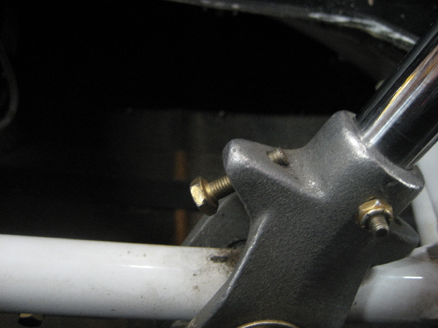
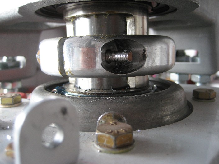
The following week I was off to Connecticut and of course now the first thing on this students ship that I checked was his locking collar. When I applied downward pressure on the collar with a piece of wood and a fulcrum the collar slipped down easily. We checked the torque on the nut and it turned and turned and turned but would not tighten. It took us nearly an hour to get the locknut with stripped threads off the bolt and as you can clearly see in the photo below the installer had used a bolt that was the next size longer than called for in the factory specs. When the nut was tightened it ran out of threads and rode up
onto the shank of the bolt stripping the nut's threads. With the
threads stripped the collar could not apply the required clamping
force onto the main rotor shaft. It could have eventually slid
down to the point that the forks could clear the collar, rotate,
and jam the collective in the full up-collective position. |
||||||
 |
||||||
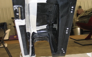
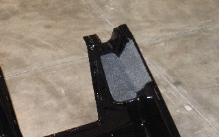
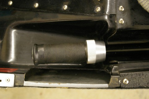
I urge everyone to check their collars prior to flight. This series of loose collars is not common because I have only found one loose clamping ring since. Collective Pocket. There is one area on the Rotorway where sometimes there is not enough clearance for the pilots left hand during the initiation of an auto-rotational descent. This is the area of the left collective pocket against the outer wall of the cabin. If the throttle is too close to allow the back of the pilot's hand and knuckles to be able to fully lower the collective into the pocket to achieve full negative pitch on the main rotor blades, some adjustment or modification to this area may be desireable. During auto training the student might be forced to slide his/her hand to the front end of the throttle and hold it with the tips of the fingers if there is not enough room in this area. I have found that a Dremmel tool with an abrasive disc cutter is the tool of choice for this simple modification. I make a cut from the front of the pocket to the rear on the flat bottom just inboard of the curved section where the fiberglass makes the transition from the horizontal floor to the vertical wall of the pocket. I then cut both sides up to the top of the pocket and then out to within about 1/4" inboard from the outer body skin panel. I then finish the removal by cutting along the outer body panel and about 1/4" in from the edge. I leave the 1/4" piece so that there is something to attach new fiberglass to when the new pocket is later formed. This is usually accomplished by utilizing the piece of fiberglass that was removed but can now be moved outward as far as possible to allow clearance for the pilots hand and knuckles when the collective is fully lowered. It can then be glassed in, smoothed and painted for a factory finish. Since we usually do not take the time to re-glass the pocket during training, we place some duct tape over the cut fiberglass edges to protect the pilots knuckles. Check the fit on your collective and determine if you can fully
lower it into the pocket with your hand around the throttle. I
want to thank Todd Mason for sending the below photo of his side
pocket with the section removed. This gives him the needed hand
clearance for autos and he can take care of the esthetics later,
SAFETY FIRST!!!!!! |
||||||
|
||||||
|
||||||
| DISCLAIMER:
The material on each page is the opinion of the author only and
any actions taken by the reader relating to information on this
site is the responsibility of the builder. |