 |
HINTS AND TIPS The Buttons below will take you through the different hints and tips that I feel will make your helicopter safer and more reliable. |
Exhaust Heat Shields
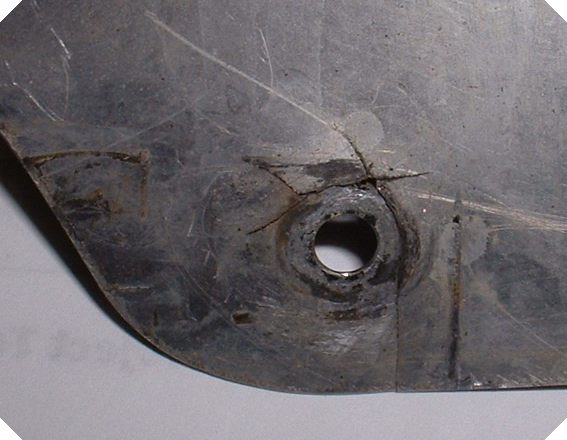
| Engine exhaust heat shields. These flat pieces of aluminum are intended to shield the plastic fuel tanks that are just in front of them from the hot exhaust headers. One simple way to strengthen the attach point is to add a second piece of aluminum of a couple of inches diameter and secure it with 6 or 8 rivets to the original shield. This spreads the stress forces out and I have not seen a modified shield crack. An interesting point to notice on the photo below is that the builder allowed the heat shield to become scratched during handling. We often hear about stress risers when dealing with metal objects and vibrations. In the photo below you can clearly see where the cracks in the heat shield occurred, along shallow scratches in the surface of the heat shield. Take note that if your metal components become scratched those scratches could become stress risers leading to a component failure while in flight. Scratches should be buffed out to prevent stresses from being concentrated along their lines.
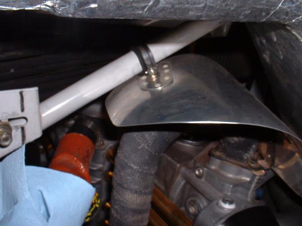
This photo shows a reinforced heat shield. A second piece of aluminum has been riveted to the original one before any cracking occurred, it is not a repair.
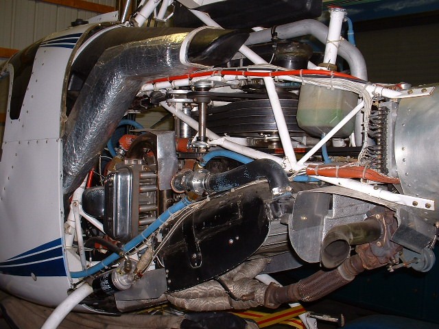
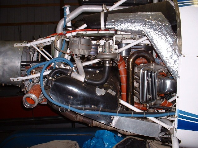
Notice the above heat shield extends down past the exhaust manifold gasket. In the photos below one can see some of the modifications that I imstalled on my early Exec. I replaced the heat wrap with stainless steel covers that completely surrounded the exhaust but had vents to allow the heat to escape both at the top and bottom. They gave me hundreds of hours of service without a single problem. Note that these shields were definately heavier than the factory suggested method. Several builders have asked me about the Turbo on my Exec. Photo below You can see the turbo, the first electric clutch (1992)on a Rotorway, my own back-side idler from around 1990. The electrical negative buss. Heavy duty VW valve covers. The red cable is supported off the frame and goes to the master relay.
Electric clutch mechanism and SS Exhaust covers
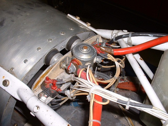
Intermittent breakers and master relay. Note that these photos were taken after I recovered the ship after it was stolen and hidden for six years. The rust was not there when it was stolen and the tail boom was painted-The thief put a new tail boom on but kept the rest of the ship as I had it. I also installed intermittent breakers on all power circuits to protect them up to the circuit breaker panels.
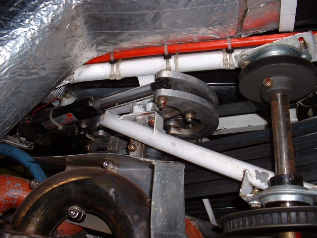
In this photo you can see the back side idler that engages the belts in toward the center by the electric actuator on the other side. I gave the plans for this first electric clutch on a Rotorway away for free. Others now manufacture this arrangement. The factory now uses the same idler configuration- pulling the belts in from the outside.
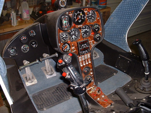
In the photo below you can see that the clutch switch was protected by a red hoop to prevent accidental actuation during flight. The critical switches on the overhead panel also were protected by similar hoops. Note the red alternator warning lights on the panel. If the belt broke or the alternator failed, the light would illuminate warning me of the failure- I could then monitor the water temp gauge to see if it was a belt failure (water pump would stop so engine would overheat) or an electrical failure.
|
| DISCLAIMER: The material on each page is the opinion of the author only and any actions taken by the reader relating to information on this site is the responsibility of the builder. |