 |
HINTS AND TIPS The Buttons below will take you through the different hints and tips that I feel will make your helicopter safer and more reliable. |
Upper Engine Mount
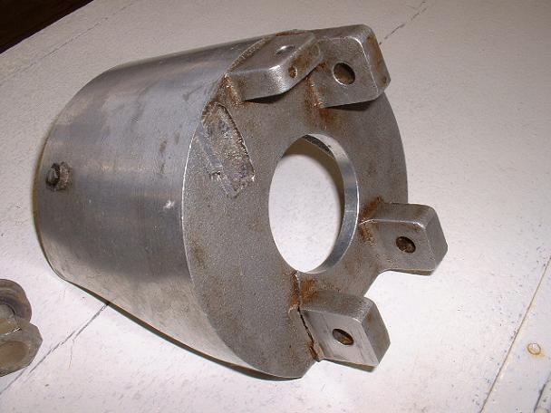
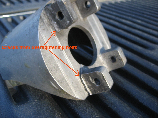
Do not tighten the upper engine mount adjustment slider through-bolts more than directed by the factory unless you fabricate and install bushings between the inside space of the inner engine mount. Tightening these two bolts excessively deflects the brittle aluminum casting and will cause it to crack. Here is a photo of an inner ear that I found down inside of the engine pulley on a secondhand ship. You can also substitute front through-bolt for 2shorter ones, each with their own lock nuts and washers that can be tightened, thereby clamping the respective halves of the upper engine mounts together with no danger of cracking the mount.
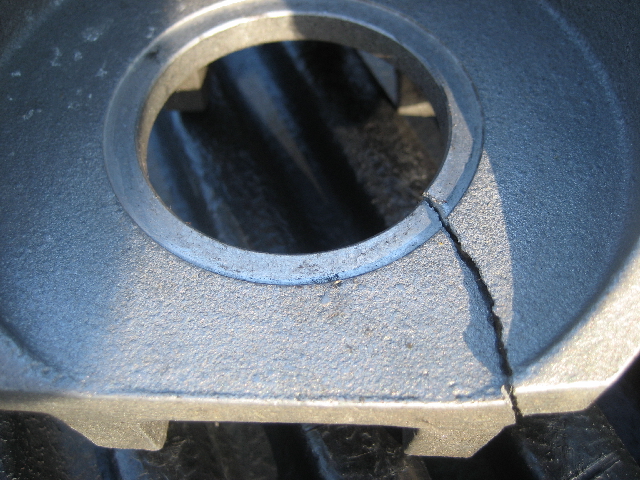
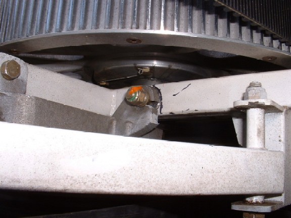
Notice that not only did the mount ear break off but the front of the bearing cup was cracked as well by over-tightening the through bolts. Below
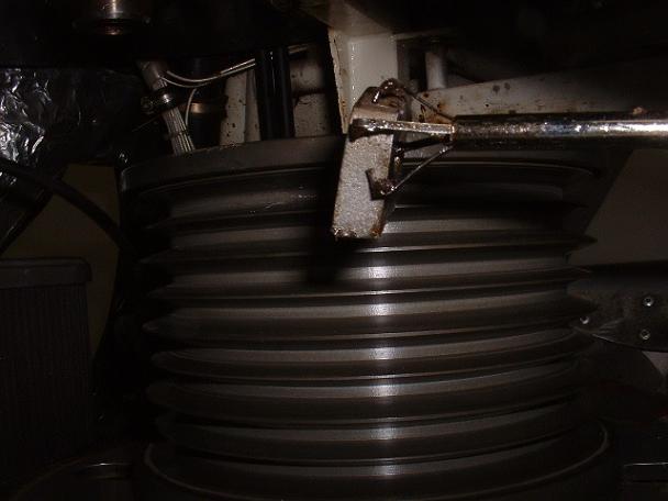
The above photo is what I saw on my airworthiness inspection. The hairline crack told the story so when I removed the engine mount I discovered the ear missing on the bearing cup. I then had to find it because I suspected that it had fallen down inside of the bearing housing and and was hiding out of sight under the bearing cup. The broken ear would have been held captive by the rear-through bolt until the bolt was removed. Once the bolt was taken out at some time in the past by a pryor owner, the broken ear fell down and lodged under the engine pulley. It showed wear marks from the bottom of the pulley rubbing against it as the engine ran. I had a real ordeal trying different ways to grab it and get it out because, being aluminum, a magnet would not work to catch it. It took around 2 hours to fish it out.
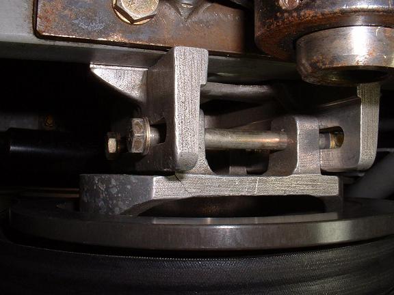
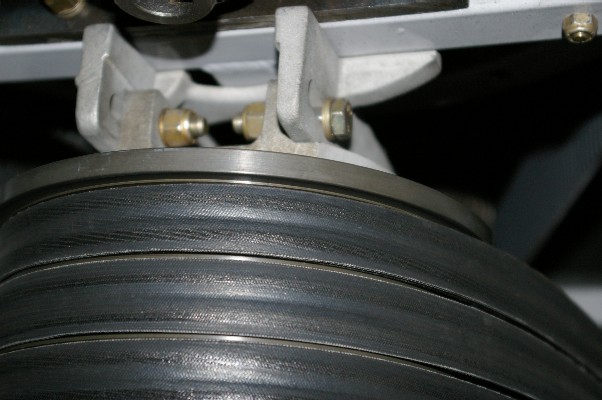
The photo below was sent to me by Todd Mason. It shows how he uses two short AN bolts with lock nuts and washers in the front slots of the engine mount (where they can be reached easily) to actually clamp the two pieces of the upper engine mount firmly together relieving a lot of pressure that is usually carried by the engine adjusting bolt alone. This is a much better solution than the factory configuration and applies no lateral forces on the mount castings that could cause them to crack. The long bolt is still used on the rear slots so it must be kept only snug to avoid cracking the castings (it should apply no clamping pressure between the castings). The front bolts in this configuration need to be loosened for belt tension adjustments and then tightened after the adjustment is made.
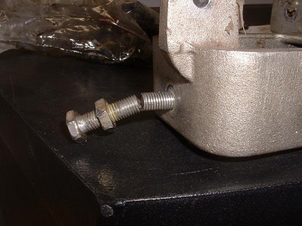
While I am on the subject of engine mounts, the following photo is of an engine adjustment bolt that has galled (welded itself) into the aluminum. Steel bolt threads into aluminum can gall and the bolt will no longer be able to be unthreaded. I have seen this happen so that when you turn the bolt to adjust the engine forward, the aluminum threads pull out with the it and you are left with a problem. In the case of the photo, the second owner tried to adjust the engine but the bolt would not turn. With his effort the bolt finally snapped. I have always suggested the use of anti-seize on this bolt but to prevent galling but you should check with the factory before deciding for yourself. If you have the upper engine mount out I suggest that you get a new extra jam nut that will fit the adjustment bolt. Rough up and clean one face of the nut and the inside face of the aluminum housing around the bolt hole. Then thread the adjustment bolt into the hole and have the threads coated with anti-seize. Apply epoxy to the cleaned face of the nut and the aluminum housing on the inside and then screw the new jamb nut onto the end of the bolt and FINGER tight up against the inner surface of the upper engine mount. It must not be more than finger tight or it will lock (JAM) the bolt threads against the engine mount. The anti-seize should prevent the epoxy from adhering to the bolt threads so that the bolt can be turned. Once the epoxy has set, you now have a steel nut on the inside face of the engine mount that the bolt will pull against as it pushes the engine forward. I use anti-seize on the bolt to keep the aluminum threads from galling.
The photo below shows the other end of the outer upper engine mount where it bolts to the frame cross tube. This photo was taken during my pre-instuction airworthiness inspection on a Rotorway Exec 162F that the owner had been flying. I was there to provide autorotation training. This broken mounting flange should have been found by the pilot.
|
| DISCLAIMER: The material on each page is the opinion of the author only and any actions taken by the reader relating to information on this site is the responsibility of the builder. |